
canadian
sy in progress
I've been researching this for a while and will be using the following method to install an electric fan once I gather all the parts. Most people use the Ford ToreAss 2 speed fan since it flows a ton of air. I believe that this method will work with that fan. With that said, on to the fun.
The first thing you are going to need is a Volvo fan relay. Most modern Volvos will have this up near the core support, and some will have it mounted directly to the fan shroud itself. Here's what it looks like:
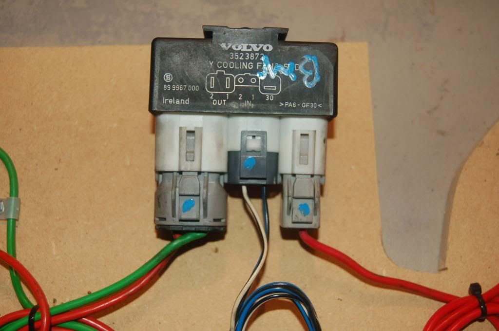
The relay will support two speed fans (or two single speed fans if you wanted). From right to left you see:
1) 12V from battery. You should run a line from the battery to a circuit breaker, then to this feed.
2) blk/blu - this is the ground for the low speed wiring
3) blk/wht - this is the ground for the high speed wiring
4) grn - this is the 12v lead to the low speed side of the fan
5) red - this is the 12v lead to the high speed side of the fan
The Volvo relay pack takes care of switching from low to high side by grounding either the blk/blu, or blk/wht wire. Do not ground both of them at the same time. This will ensure that you are never running both the low and high speed of the fan at the same time.
Why use this relay setup? Well, because it's made by Volvo, and you can get them cheap at the bone yard. Get as much connected wire as you can from the donor car.
Tonight I put together a few options just to see if my research worked, and to get some peer review here. Typically people will run the positive side of the battery through the ignition switched relay and then to the fan. That requires a high amp relay to handle things. The Volvo is set up to handle the current draw, but you always want to have some protection on the 12v feed side. You can use a resettable circuit breaker, or a maxi-fuse to protect it.
So here's what I came up with for testing. This is the basic layout:
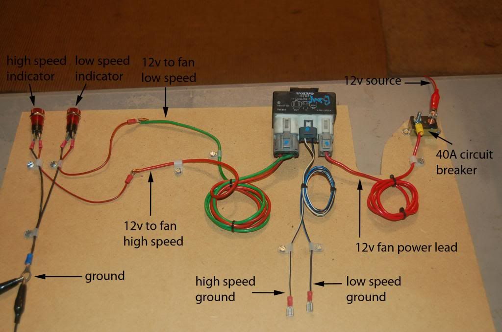
Pretty straight forward. Top right has the battery source connected to a 30A resettable breaker. Bottom left has ground that would go to the battery. Now, for this demonstration I used to 12v bulbs to simulate the low and high side of the fan.
Here's the up close look at the wiring and my fan speed simulator bulbs:

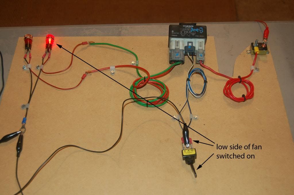
Here's what it looks like if the low side of the relay pack was grounded:

Here's what it looks like with the high side of the relay grounded:

OK, so how do I wire it all up?
In the above diagram, everything is laid out pretty clearly, but you need to be able to ground either the low or high side triggers in the middle. There are a few options here
Option 1: Use a toggle swtich
If you wanted to use a toggle switch, you'd need a single pole, double throw switch. The middle post would be wired to a known ground, and the outer posts would be wired to the relay pack like this:

Now, when you switched the toggle to the low side and grounded the relay, the low side of the fan would come on like this:
PROS: No need for a temperature sensor, easier wiring.
CONS: You are in charge of operating the fans. If you forget to turn them on, you'll overheat. If you forget to turn them off, your battery will die. Note that in this system, it's all manual. There is no switched power to the system.
Option 2
Option 2 consists of replacing the toggle switch you see here with a temperature switch from a BMW. Here's what the switch looks like:

This sensor is installed in almost all BMW's. You'll find it in the upper passenger side of the radiator. Inside the connector looks like this:

The top-center post is the common ground. T2 is grounded when the sensor reaches it's lower limit. T1 is grounded when it hits the higher limit. RockAuto has a temp sensor that turns on at 176 and high at 190 degrees for those of you running a 160* thermostat.
The only drawback to this sensor is that it's threaded 14x1.5mm. You'd need to buy a tap, drill out a fitting to 1/2" and tap it. Not a big deal. I think JagsThatRun also sells an inline radiator hose adapter for these fittings.
Going forward in this thread, assume that the three way toggle switch has been replaced with the BMW temp sensor above. Technically you could leave the toggle switch in place, but the electric fan will come on as soon as 12v is applied. Not always good when trying to start the truck.
OK, so you replaced the toggle switch with the BMW temp sensor. The problem now is that when you shut off the truck, the fan will continue running until the temp sensor sees the coolant temp drop below it's low temp turn on point. For instance, if the low side turn on was 176*, the way it's wired now it would still run until the temp dropped to 175*.
Since the water pump isn't running, it may take a while for the sensor to see the lower temperature. It's entirely possible that it will drain your battery before that happens.
How do I avoid draining my battery?
Since the temp sensor uses a common ground in order to ground the Volvo relay pack, we need to interrupt this until a "turn on" signal is provided. How do we do this? We use a switched 12v source and a relay. Here's how the relay is going to be wired:

The trigger on post 86 needs to come from a switched ignition source. That will then allow the current to flow from post 87 to a ground. You could run this off your ignition switch, but a better idea is to ground your intercooler pump relay, and then use the power lead to the intercooler pump to trigger the relay.
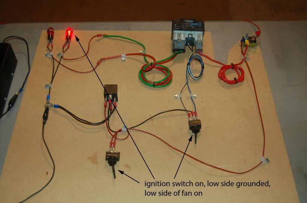
The photo below shows how the wiring would be set up to use a switched 12v to allow the signal from the temp sensor to be grounded:

I have wired up a 12v source to a single pole single throw switch. When it's off, no current flows to post 86 on the relay. Note that the center post of the three way switch is wired to post 87 on the relay. This is where the ground gets interrupted.
Here's a better view:

With the ignition switch off, even if the fan should be on, it won't be able to turn on. This would be the situation when your fan is running, but you shut the truck off:

Now, with the ignition switch on, if the temperature sender hasn't reached it's low operating point, the fans will stay off:

Now, with the ignition switch on, and the temperature sensor hitting it's low point, it will ground the low side of the Volvo relay and the low side of the fan will come on:
And if the fan can't keep the truck cool and it reaches the temperature senders high set point, it will flip over and turn on the high speed fan:

Well, that's it. I have all of the photos in my Photobucket album if you need them. I still need to get myself a complete Volvo fan setup, BMW temp sensor with 176/190 set points, and a decent wiring connector for the BMW temp sensor.
You could replace the BMW temp sensor with any other sensor provided it switches between two different ground wires depending on the temperature. I hope this helps somebody out there.
Clarification
After discussing with DaveP, he had me test grounding both the low and high side of the relay pack. If the low side is grounded, the low speed fan is triggered and vice-versa for the high side. If BOTH sides are grounded, only the high speed 12v is triggered. He clarified for me that most temp sensors will ground both connections once the high set point is reached. It doesn't switch between the two.
The first thing you are going to need is a Volvo fan relay. Most modern Volvos will have this up near the core support, and some will have it mounted directly to the fan shroud itself. Here's what it looks like:
The relay will support two speed fans (or two single speed fans if you wanted). From right to left you see:
1) 12V from battery. You should run a line from the battery to a circuit breaker, then to this feed.
2) blk/blu - this is the ground for the low speed wiring
3) blk/wht - this is the ground for the high speed wiring
4) grn - this is the 12v lead to the low speed side of the fan
5) red - this is the 12v lead to the high speed side of the fan
The Volvo relay pack takes care of switching from low to high side by grounding either the blk/blu, or blk/wht wire. Do not ground both of them at the same time. This will ensure that you are never running both the low and high speed of the fan at the same time.
Why use this relay setup? Well, because it's made by Volvo, and you can get them cheap at the bone yard. Get as much connected wire as you can from the donor car.
Tonight I put together a few options just to see if my research worked, and to get some peer review here. Typically people will run the positive side of the battery through the ignition switched relay and then to the fan. That requires a high amp relay to handle things. The Volvo is set up to handle the current draw, but you always want to have some protection on the 12v feed side. You can use a resettable circuit breaker, or a maxi-fuse to protect it.
So here's what I came up with for testing. This is the basic layout:
Pretty straight forward. Top right has the battery source connected to a 30A resettable breaker. Bottom left has ground that would go to the battery. Now, for this demonstration I used to 12v bulbs to simulate the low and high side of the fan.
Here's the up close look at the wiring and my fan speed simulator bulbs:
Here's what it looks like if the low side of the relay pack was grounded:
Here's what it looks like with the high side of the relay grounded:
OK, so how do I wire it all up?
In the above diagram, everything is laid out pretty clearly, but you need to be able to ground either the low or high side triggers in the middle. There are a few options here
Option 1: Use a toggle swtich
If you wanted to use a toggle switch, you'd need a single pole, double throw switch. The middle post would be wired to a known ground, and the outer posts would be wired to the relay pack like this:
Now, when you switched the toggle to the low side and grounded the relay, the low side of the fan would come on like this:
PROS: No need for a temperature sensor, easier wiring.
CONS: You are in charge of operating the fans. If you forget to turn them on, you'll overheat. If you forget to turn them off, your battery will die. Note that in this system, it's all manual. There is no switched power to the system.
Option 2
Option 2 consists of replacing the toggle switch you see here with a temperature switch from a BMW. Here's what the switch looks like:
This sensor is installed in almost all BMW's. You'll find it in the upper passenger side of the radiator. Inside the connector looks like this:
The top-center post is the common ground. T2 is grounded when the sensor reaches it's lower limit. T1 is grounded when it hits the higher limit. RockAuto has a temp sensor that turns on at 176 and high at 190 degrees for those of you running a 160* thermostat.
The only drawback to this sensor is that it's threaded 14x1.5mm. You'd need to buy a tap, drill out a fitting to 1/2" and tap it. Not a big deal. I think JagsThatRun also sells an inline radiator hose adapter for these fittings.
Going forward in this thread, assume that the three way toggle switch has been replaced with the BMW temp sensor above. Technically you could leave the toggle switch in place, but the electric fan will come on as soon as 12v is applied. Not always good when trying to start the truck.
OK, so you replaced the toggle switch with the BMW temp sensor. The problem now is that when you shut off the truck, the fan will continue running until the temp sensor sees the coolant temp drop below it's low temp turn on point. For instance, if the low side turn on was 176*, the way it's wired now it would still run until the temp dropped to 175*.
Since the water pump isn't running, it may take a while for the sensor to see the lower temperature. It's entirely possible that it will drain your battery before that happens.
How do I avoid draining my battery?
Since the temp sensor uses a common ground in order to ground the Volvo relay pack, we need to interrupt this until a "turn on" signal is provided. How do we do this? We use a switched 12v source and a relay. Here's how the relay is going to be wired:
The trigger on post 86 needs to come from a switched ignition source. That will then allow the current to flow from post 87 to a ground. You could run this off your ignition switch, but a better idea is to ground your intercooler pump relay, and then use the power lead to the intercooler pump to trigger the relay.
The photo below shows how the wiring would be set up to use a switched 12v to allow the signal from the temp sensor to be grounded:
I have wired up a 12v source to a single pole single throw switch. When it's off, no current flows to post 86 on the relay. Note that the center post of the three way switch is wired to post 87 on the relay. This is where the ground gets interrupted.
Here's a better view:
With the ignition switch off, even if the fan should be on, it won't be able to turn on. This would be the situation when your fan is running, but you shut the truck off:
Now, with the ignition switch on, if the temperature sender hasn't reached it's low operating point, the fans will stay off:
Now, with the ignition switch on, and the temperature sensor hitting it's low point, it will ground the low side of the Volvo relay and the low side of the fan will come on:
And if the fan can't keep the truck cool and it reaches the temperature senders high set point, it will flip over and turn on the high speed fan:
Well, that's it. I have all of the photos in my Photobucket album if you need them. I still need to get myself a complete Volvo fan setup, BMW temp sensor with 176/190 set points, and a decent wiring connector for the BMW temp sensor.
You could replace the BMW temp sensor with any other sensor provided it switches between two different ground wires depending on the temperature. I hope this helps somebody out there.
Clarification
After discussing with DaveP, he had me test grounding both the low and high side of the relay pack. If the low side is grounded, the low speed fan is triggered and vice-versa for the high side. If BOTH sides are grounded, only the high speed 12v is triggered. He clarified for me that most temp sensors will ground both connections once the high set point is reached. It doesn't switch between the two.
Last edited:
